C51 Kit Evaluation
Monday, February 27th, 2017
STC Website: stcmcu.com
89C52RC Datasheet: English version
STC-ISP: Version 6.85P (Windows)
Mac/Linux Programmer: Python script
SDCC: Homepage
Dev Boards: Available here
Dev Board Schematic: In the /datasheet folder
Earlier this summer I was wanting to brush up on 8051 programming. Why the 8051? Mostly because of its ubiquity, but also because some of the modern variants are pretty heavily loaded with flash and ram and IO. The STC 8051 clone used on the board in this article has a whopping 32 IO pins – in a DIP40 package! Further, the base circuit to support an 8051 is incredibly simple (see page 11 of the datasheet referenced above). If all of that wasn’t enough, the IO is all 5 volt tolerant, making this an ideal controller for retrocomputing-related projects.
After shopping around for a suitable 8051 developer board, there were a number of interesting options available, but only one fit all of my requirements:
- Come as an unassembled kit
- Contain a modernized variant of the 8051
- Cost < 20 USD
- Include at least a 16×2 LCD and some buttons
The kit I picked is based around the STC 89C52RC. STC has a very interesting website (see above) The best vendor for these seems to be ICStation.com, who also sell a huge array of other really cool looking kits. They sell this particular kit for around 6 USD.
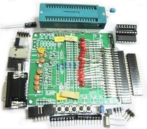
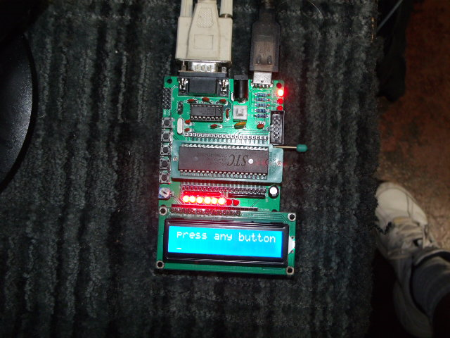
The kit arrives, well, as a kit. It’s in pieces and has to be assembled. There are no instructions, but the board is silkscreened well enough that they’re not needed anyway. 2 hours and several second-degree burns later, you have this:
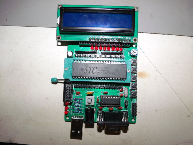
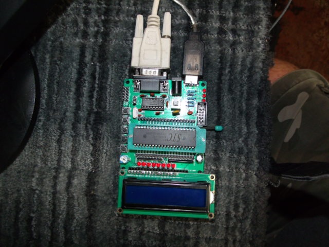
Note that the DB9 serial port is for programming, the USB port is strictly for power. I didn’t experiment with the ISP port, I don’t have the cables on hand for that. For the USB Power connection, I used a USB extension M-F and and old iphone wall adapter. For serial, I used a standard USB->Serial adapter.
Now that the kit is assembled, let’s talk a bit about toolchain. There are a few things we’ll need:
- An assembler/compiler – this would be SDCC (see above)
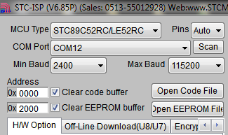
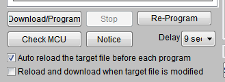
- An uploader to put our binary on the device – this would be STC-ISP (see above)
On Windows, I found the combination of SDCC and STC-ISP to be workable. If you choose to use STC-ISP, make sure to select the correct device and com port.
While writing this article and looking for Mac/Linux equivalents, I found out about STCFlash (see above) while deciphering the information here. SDCC+STCFlash may actually be a better combination on Windows as well – as of the time of this writing I have yet to try it.
On to the example code, then. Copy the below and save it as “test.cpp”.
Compile:
sdcc test.cpp
This should produce an Intel Hex file called test.ihx, which you can then upload:
python stcflash.py test.ihx
And now you’re ready to while away the hours trying to figure out which button is the right one!
test.cpp:
#include
__sbit __at (0x92) rs; // P1.2 Register select (RS)
__sbit __at (0x91) rw; // P1.1 Read write (RW) pin
__sbit __at (0x90) en; // P1.0 Enable (EN) pin__sbit __at (0xB5) but0; // P3.5
__sbit __at (0xB4) but1; // P3.4
__sbit __at (0xB3) but2; // P3.3
__sbit __at (0xB2) but3; // P3.2const char LCD_8_BIT_1_LINE = 0x30;
const char LCD_8_BIT_2_LINES = 0x38;
const char LCD_ENTRY_MODE = 0x06;
const char LCD_DISPLAY_ON_CURSOR_BLINK = 0x0f;
const char LCD_CLEAR_DISPLAY = 0x01;
const char LCD_SET_POSITION = 0x80;char text[]={"press any button"};
char text2[]={"wrong button"};void delay(unsigned int time)
{
unsigned int i,j;
for(i=0;i < time;i++) for(j=0;j<5;j++); } void lcdcmd(unsigned char value) { P2=value; rs = 0; rw = 0; en = 1; delay(50); en=0; delay(50); } void display(unsigned char value) { P2=value; rs = 1; rw = 0; en = 1; delay(50); en=0; delay(50); } void lcd_cls(void){ lcdcmd(LCD_CLEAR_DISPLAY); delay(50); lcdcmd(LCD_ENTRY_MODE); delay(50); lcdcmd(LCD_SET_POSITION); delay(50); } void initialize(void) { P2=0x00; //Port 1 is used as output port P3=0xff; //Port 3 is input delay(15000); display(0x30); delay(4500); display(0x30); delay(300); display(0x30); delay(650); lcdcmd(LCD_8_BIT_2_LINES); delay(50); lcdcmd(LCD_DISPLAY_ON_CURSOR_BLINK); delay(50); lcd_cls(); } void lcd_print(char *printtext){ unsigned int i; i=0; while(printtext[i]!='\0'){ display(printtext[i]); //delay(20); i++; } } void main() { initialize(); while (1){ lcd_cls(); lcd_print(text); lcdcmd(0xc0); while (but0==1 && but1==1 && but2==1 && but3==1){} lcd_print(text2); while (but0==1 && but1==1 && but2==1 && but3==1){} } }